How To Test A Diode
Diodes are crucial components in electronic circuits, and testing them is essential to ensure they function correctly. A faulty diode can cause a range of problems, from malfunctioning devices to complete system failures. To test a diode, you need to understand its basic operation and the methods used to verify its functionality. In this article, we will explore the process of testing a diode, starting with the fundamentals of diode testing. We will discuss the different methods for testing a diode, including the use of multimeters and other specialized equipment. Additionally, we will delve into the interpretation of test results, helping you to identify whether a diode is functioning correctly or not. By understanding these concepts, you will be able to effectively test a diode and ensure the reliability of your electronic circuits. Let's begin by understanding the basics of diode testing.
Understanding Diode Testing
Understanding diodes and their testing is crucial in the field of electronics. Diodes are fundamental components in electronic circuits, and their proper functioning is essential for the overall performance of the circuit. In this article, we will delve into the world of diodes and explore the importance of testing them. We will begin by explaining what a diode is and its function in electronic circuits. This understanding will provide a solid foundation for the subsequent discussion on the importance of testing a diode and the necessary precautions to take before conducting the test. By the end of this article, you will have a comprehensive understanding of diode testing and its significance in ensuring the reliability and efficiency of electronic devices. So, let's start by understanding what a diode is and its function.
What is a Diode and Its Function
A diode is a type of semiconductor device that allows current to flow in one direction while blocking it in the other. It is essentially a one-way street for electricity, permitting the flow of current from the anode (positive side) to the cathode (negative side), but not in the reverse direction. The primary function of a diode is to control the flow of electrical current, and it is commonly used in a wide range of applications, including power supplies, rectifiers, voltage regulators, and electronic switches. Diodes can be used to convert AC (alternating current) to DC (direct current), regulate voltage levels, and protect electronic circuits from voltage spikes and surges. In essence, diodes act as a gatekeeper, allowing or blocking the flow of current as needed, making them a crucial component in modern electronics.
Importance of Testing a Diode
Testing a diode is crucial in ensuring the proper functioning of electronic circuits. A diode is a semiconductor device that allows current to flow in one direction while blocking it in the other, and its failure can lead to a range of problems, including short circuits, overheating, and even complete system failure. By testing a diode, you can determine whether it is functioning correctly, identify any faults or defects, and prevent potential problems from arising. There are several methods for testing a diode, including using a multimeter, which can measure the diode's voltage drop and resistance, and observing its behavior under different conditions. Testing a diode is particularly important in applications where reliability and safety are critical, such as in medical devices, aerospace, and automotive systems. In these situations, a faulty diode can have serious consequences, and regular testing can help to ensure that the device is functioning correctly and safely. Furthermore, testing a diode can also help to identify any potential issues with the circuit or system as a whole, allowing for prompt repairs and maintenance. Overall, testing a diode is an essential step in ensuring the reliability, safety, and efficiency of electronic circuits, and it should be a regular part of any maintenance or troubleshooting routine.
Precautions Before Testing a Diode
When testing a diode, it's essential to take certain precautions to ensure accurate results and prevent damage to the diode or the testing equipment. First, always unplug the circuit or device being tested from the power source to prevent electrical shock or damage to the diode. Next, verify that the diode is properly identified and its specifications are known, as different types of diodes have varying voltage and current ratings. Use a multimeter with a diode test function or a dedicated diode tester, and set the multimeter to the correct range and function to avoid damaging the diode. Additionally, avoid touching the diode's leads or terminals with your bare hands, as the oils from your skin can damage the diode or affect the test results. When testing a diode in a circuit, ensure that all other components are disconnected or isolated to prevent interference or false readings. It's also crucial to follow proper testing procedures and take note of the diode's orientation, as incorrect testing can lead to incorrect results or damage to the diode. By taking these precautions, you can ensure accurate and reliable test results, and prevent damage to the diode or testing equipment.
Methods for Testing a Diode
When testing a diode, it's essential to have a clear understanding of the methods involved to ensure accurate results. There are several approaches to testing a diode, each with its own advantages and limitations. Three primary methods include using a multimeter in diode test mode, utilizing a multimeter in ohms function, and employing a diode tester or specialized equipment. These methods cater to different testing needs and provide distinct insights into the diode's functionality. By understanding these approaches, individuals can effectively assess the condition and performance of a diode. To begin with, one of the most straightforward and widely used methods is using a multimeter in diode test mode, which provides a quick and reliable way to test a diode's forward and reverse bias characteristics.
Using a Multimeter in Diode Test Mode
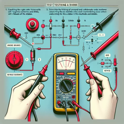
When using a multimeter in diode test mode, the goal is to measure the forward voltage drop across the diode and check for any signs of damage or malfunction. To do this, set the multimeter to the diode test function, usually indicated by a diode symbol, and ensure that the multimeter leads are connected to the correct terminals of the diode. The red lead typically goes to the anode, while the black lead goes to the cathode. Once connected, the multimeter will display the forward voltage drop, which should be around 0.7V for a standard silicon diode. If the reading is significantly higher or lower than this value, it may indicate a faulty diode. Additionally, if the multimeter displays an open circuit or infinite resistance, it could mean that the diode is shorted or damaged. It's also important to note that some multimeters may have a specific setting for testing Schottky diodes, which have a lower forward voltage drop than standard diodes. By following these steps and understanding the expected readings, you can effectively use a multimeter in diode test mode to diagnose and troubleshoot diode-related issues in electronic circuits.
Using a Multimeter in Ohms Function
When using a multimeter in ohms function to test a diode, it's essential to understand the basics of how the multimeter works and how to interpret the readings. In ohms function, the multimeter sends a small current through the diode and measures the resulting voltage drop. The multimeter then calculates the resistance of the diode based on Ohm's law. To use a multimeter in ohms function, start by setting the multimeter to the ohms function and selecting the appropriate range. Next, touch the multimeter leads to the diode, making sure to observe the correct polarity. The multimeter will display a reading in ohms, which indicates the resistance of the diode. If the diode is forward-biased, the multimeter should display a low reading, typically in the range of 0.1 to 1 ohm. If the diode is reverse-biased, the multimeter should display a high reading, typically in the range of 1 megaohm or higher. If the multimeter displays an open circuit or infinite reading, it may indicate that the diode is faulty or has been damaged. It's also important to note that some multimeters may have a diode test function, which can provide a more accurate reading of the diode's forward voltage drop. When using a multimeter in ohms function, it's crucial to be aware of the potential for false readings due to the multimeter's internal resistance and the diode's internal capacitance. To minimize errors, use a multimeter with a high input impedance and take multiple readings to ensure accuracy. By following these steps and understanding the basics of how the multimeter works, you can use a multimeter in ohms function to accurately test a diode and determine its condition.
Using a Diode Tester or Specialized Equipment
Here is the paragraphy: When a diode tester or specialized equipment is used, the process of testing a diode becomes more precise and efficient. A diode tester is a device specifically designed to test diodes, and it can provide a more accurate reading of the diode's condition. This type of tester can identify whether the diode is functioning correctly, open, or shorted. Specialized equipment, such as a multimeter with a diode test function or an oscilloscope, can also be used to test diodes. These devices can provide a more detailed analysis of the diode's behavior and can help identify any potential issues. For example, a multimeter can measure the diode's forward voltage drop, reverse leakage current, and junction capacitance, while an oscilloscope can display the diode's waveform and help identify any distortion or anomalies. By using a diode tester or specialized equipment, individuals can ensure that their diodes are functioning correctly and make any necessary repairs or replacements. This is particularly important in applications where diodes play a critical role, such as in power supplies, audio equipment, and medical devices. In these situations, a faulty diode can have serious consequences, and using a diode tester or specialized equipment can help prevent such issues. Overall, using a diode tester or specialized equipment is an effective way to test diodes and ensure that they are functioning correctly.
Interpreting Diode Test Results
Interpreting diode test results is a crucial step in diagnosing and repairing electronic circuits. When testing a diode, it's essential to understand the readings obtained to determine its condition. A diode test typically involves measuring the voltage drop across the diode in both forward and reverse bias conditions. To accurately interpret the results, it's vital to comprehend the differences between forward and reverse bias readings. This knowledge will enable you to identify whether a diode is functioning correctly, faulty, or short-circuited. By understanding forward and reverse bias readings, you can troubleshoot common issues that may arise during diode testing, such as incorrect voltage readings or inconsistent results. In this article, we will explore how to interpret diode test results, including understanding forward and reverse bias readings, identifying a good, bad, or short-circuited diode, and troubleshooting common issues with diode testing. Let's start by understanding forward and reverse bias readings.
Understanding Forward and Reverse Bias Readings
When interpreting diode test results, it's essential to understand the concept of forward and reverse bias readings. A forward-biased diode is one where the positive terminal of the multimeter is connected to the anode of the diode, and the negative terminal is connected to the cathode. In this configuration, the diode is essentially "turned on," allowing current to flow through it with minimal resistance. A typical forward-biased reading on a multimeter is around 0.5 to 0.8 volts, depending on the type of diode being tested. On the other hand, a reverse-biased diode has the positive terminal of the multimeter connected to the cathode and the negative terminal connected to the anode. In this case, the diode is "turned off," and the multimeter will typically show a very high resistance reading, often in the range of several kilohms or even megohms. Understanding these forward and reverse bias readings is crucial in determining whether a diode is functioning correctly or not. By comparing the readings to the expected values, you can quickly identify if a diode is shorted, open, or functioning as expected. For instance, if a diode shows a very low resistance reading in both forward and reverse bias configurations, it may be shorted, while a diode that shows no reading at all in either configuration may be open. By analyzing these readings, you can make informed decisions about the diode's condition and take necessary actions to repair or replace it.
Identifying a Good, Bad, or Short-Circuited Diode
When testing a diode, it's essential to identify whether it's good, bad, or short-circuited. A good diode will show a voltage drop of around 0.7 volts when forward-biased and an open circuit when reverse-biased. If the diode is bad, it may show a voltage drop of 0 volts or a very low reading when forward-biased, indicating a short circuit. On the other hand, if the diode is short-circuited, it will show a voltage drop of 0 volts in both forward and reverse bias, indicating that the diode is allowing current to flow in both directions. To confirm, you can also use the diode test function on your multimeter, which will display a low reading (usually around 0.7 volts) for a good diode and a high reading (usually around 1) for a bad or short-circuited diode. Additionally, you can also perform a continuity test to check for any shorts or opens in the diode. By analyzing the test results, you can determine the condition of the diode and decide whether it needs to be replaced or not.
Troubleshooting Common Issues with Diode Testing
Troubleshooting common issues with diode testing can be a challenging task, but with the right approach, it can be simplified. One of the most common issues encountered during diode testing is incorrect polarity, which can lead to false readings or damage to the diode. To troubleshoot this issue, ensure that the multimeter leads are connected correctly to the diode, with the positive lead connected to the anode and the negative lead connected to the cathode. Another common issue is the presence of parasitic capacitance, which can affect the accuracy of the test results. To mitigate this, use a high-frequency multimeter or a specialized diode tester that can filter out capacitance. Additionally, ensure that the diode is properly isolated from other components in the circuit to prevent interference. If the diode is still not testing correctly, check for physical damage, such as cracks or corrosion, which can affect its performance. In some cases, the diode may be faulty or defective, in which case it may need to be replaced. By following these troubleshooting steps, you can quickly identify and resolve common issues with diode testing, ensuring accurate and reliable results.