How To Check Continuity
Here is the introduction paragraph: Checking continuity is a fundamental skill in electronics and electrical engineering, allowing individuals to verify the integrity of circuits and identify potential issues. Continuity testing is a crucial step in troubleshooting and repairing electrical systems, and it's essential to understand the concept, tools, and techniques involved. In this article, we'll delve into the world of continuity testing, starting with the basics of what continuity means and how it's measured. We'll explore the various tools and equipment required for continuity testing, including multimeters and circuit testers. Finally, we'll provide a step-by-step guide on how to perform continuity testing, ensuring that you're equipped with the knowledge and skills to tackle even the most complex electrical systems. By understanding the concept of continuity, you'll be well on your way to becoming proficient in continuity testing.
Understanding the Concept of Continuity
Understanding the concept of continuity is crucial in various fields, particularly in electrical engineering. Continuity refers to the uninterrupted flow of electric current through a circuit or system. In this article, we will delve into the concept of continuity, its importance in electrical systems, and its common applications. We will start by defining continuity in electrical circuits, exploring its fundamental principles and how it is measured. We will then discuss the importance of continuity in electrical systems, highlighting its role in ensuring safety and efficiency. Finally, we will examine the common applications of continuity testing, including its use in troubleshooting and maintenance. By understanding continuity, individuals can better appreciate the intricacies of electrical systems and develop the skills necessary to work with them effectively. To begin, let's define continuity in electrical circuits and explore its underlying principles.
Defining Continuity in Electrical Circuits
In electrical circuits, continuity refers to the uninterrupted flow of electric current through a conductor, such as a wire. It is a fundamental concept in understanding how circuits operate and is crucial for ensuring the safe and efficient functioning of electrical systems. Continuity is achieved when there are no breaks or interruptions in the conductor, allowing the electric current to flow freely from one point to another. In other words, continuity exists when the resistance between two points in a circuit is zero, or at least negligible. This means that the circuit is complete, and the current can flow without any obstacles or interruptions. Continuity is often checked using a multimeter or a continuity tester, which can detect even the slightest breaks or interruptions in the circuit. By verifying continuity, electricians and technicians can identify and troubleshoot issues in electrical circuits, ensuring that they operate safely and efficiently. In summary, continuity is a critical concept in electrical circuits, and understanding it is essential for designing, building, and maintaining reliable and efficient electrical systems.
Importance of Continuity in Electrical Systems
The importance of continuity in electrical systems cannot be overstated. Continuity is the uninterrupted flow of electric current through a circuit, and it is essential for the proper functioning of electrical devices and systems. Without continuity, electrical systems can malfunction, leading to a range of problems, including equipment damage, power outages, and even safety hazards. In fact, continuity is so critical that it is often considered the most important aspect of electrical system design and maintenance. When continuity is maintained, electrical systems can operate efficiently, reliably, and safely, ensuring that devices and equipment function as intended. Conversely, when continuity is disrupted, electrical systems can become unpredictable and prone to errors, leading to costly repairs, downtime, and even accidents. Therefore, ensuring continuity is a top priority for electricians, engineers, and technicians, who use various techniques and tools, such as multimeters and circuit testers, to verify continuity and identify any potential issues before they become major problems. By prioritizing continuity, electrical professionals can help prevent electrical system failures, reduce maintenance costs, and ensure the safe and reliable operation of electrical systems.
Common Applications of Continuity Testing
Continuity testing is a crucial aspect of ensuring the reliability and safety of electrical circuits and systems. The applications of continuity testing are diverse and widespread, encompassing various industries and fields. One of the most common applications is in the electrical and electronics industry, where continuity testing is used to verify the integrity of wiring and circuits in devices, appliances, and equipment. This involves checking for any breaks or faults in the circuit, which can cause malfunctions or even lead to electrical shocks. Continuity testing is also essential in the automotive industry, where it is used to diagnose and repair electrical issues in vehicles. In the construction industry, continuity testing is used to ensure that electrical wiring and circuits are properly installed and functioning correctly. Additionally, continuity testing is used in the medical field to verify the integrity of medical equipment and devices, such as defibrillators and ventilators. In the aerospace industry, continuity testing is used to ensure the reliability of electrical systems in aircraft and spacecraft. Furthermore, continuity testing is used in the manufacturing industry to test the quality and reliability of products, such as circuit boards and electrical components. Overall, continuity testing plays a vital role in ensuring the safety, reliability, and efficiency of electrical circuits and systems across various industries and applications.
Tools and Equipment for Continuity Testing
Continuity testing is a crucial process in ensuring the reliability and safety of electrical systems, circuits, and devices. It involves verifying that there are no breaks or interruptions in the flow of electric current. To perform continuity testing effectively, various tools and equipment are used. Among the most essential tools are multimeters, which provide a range of functions for measuring electrical properties. Additionally, continuity testers offer specialized features for detecting continuity issues. Furthermore, other equipment such as oscilloscopes and signal generators are used for advanced continuity testing. In this article, we will explore the functions of multimeters, the advantages of continuity testers, and the role of other equipment in continuity testing. First, let's take a closer look at multimeters and their functions.
Multimeters and Their Functions
A multimeter is a versatile tool used to measure various electrical parameters, including voltage, current, resistance, and continuity. It is an essential device for electricians, technicians, and DIY enthusiasts to diagnose and troubleshoot electrical circuits and systems. A multimeter typically consists of a digital display, a dial or button selector, and a set of probes or leads. The dial or button selector allows users to choose the desired measurement function, such as DC voltage, AC voltage, resistance, or continuity. The probes or leads are used to connect the multimeter to the circuit or component being measured. When measuring continuity, the multimeter sends a small current through the circuit and measures the resistance. If the resistance is very low, typically less than 1 ohm, the multimeter indicates continuity, usually with a beep or a flashing light. This function is useful for checking if a circuit is complete, if a wire is broken, or if a component is faulty. In addition to continuity testing, multimeters can also measure voltage, current, and resistance, making them a valuable tool for a wide range of electrical applications. By understanding how to use a multimeter and its various functions, users can quickly and accurately diagnose electrical issues and make necessary repairs.
Continuity Testers and Their Advantages
A continuity tester is a handy tool used to verify the presence of a continuous electrical path between two points in a circuit. It is an essential device for electricians, technicians, and DIY enthusiasts to ensure that their electrical connections are secure and functioning properly. The advantages of using a continuity tester are numerous. Firstly, it helps to identify any breaks or faults in the circuit, allowing for quick and efficient troubleshooting. This saves time and reduces the risk of electrical shock or fire hazards. Secondly, a continuity tester can detect the presence of short circuits, which can cause damage to equipment and pose a safety risk. By using a continuity tester, users can ensure that their electrical connections are safe and reliable. Additionally, continuity testers are often compact and portable, making them easy to use in a variety of settings, from residential to industrial environments. Overall, a continuity tester is a valuable tool that provides peace of mind and helps to prevent electrical accidents.
Other Equipment for Advanced Continuity Testing
The continuity testing process can be enhanced with the use of other specialized equipment, in addition to the basic multimeter. One such tool is the tone generator and probe, which is particularly useful for tracing wires and cables in complex systems. This device sends a unique tone through the wire, allowing the technician to identify the corresponding wire at the other end using the probe. Another useful tool is the cable tester, which can quickly identify faults in Ethernet cables, such as opens, shorts, and miswires. For more advanced testing, a time-domain reflectometer (TDR) can be used to measure the length of cables and detect faults, such as opens, shorts, and water ingress. A TDR works by sending a high-frequency signal down the cable and measuring the reflections that bounce back, allowing the technician to pinpoint the location of the fault. Additionally, a wire mapper can be used to identify the wiring configuration of a circuit, including the location of wires, cables, and connectors. This is particularly useful for troubleshooting complex systems and identifying wiring errors. Overall, these specialized tools can greatly enhance the continuity testing process, allowing technicians to quickly and accurately identify faults and make repairs.
Step-by-Step Guide to Continuity Testing
Continuity testing is a crucial step in ensuring the integrity of electrical circuits. It involves verifying that there are no breaks or interruptions in the flow of electricity, which is essential for the safe and efficient operation of electrical systems. To perform a continuity test, one must first prepare the circuit, which includes identifying the components and connections involved, disconnecting power sources, and ensuring the circuit is de-energized. Once the circuit is prepared, the next step is to conduct the continuity test using a multimeter, which involves setting the multimeter to the continuity test function and touching the leads to the circuit components. After conducting the test, it is essential to interpret the results, which involves understanding the readings on the multimeter and determining whether the circuit is continuous or not. In this article, we will provide a step-by-step guide to continuity testing, starting with preparing the circuit for continuity testing.
Preparing the Circuit for Continuity Testing
Preparing the circuit for continuity testing is a crucial step to ensure accurate and reliable results. Before starting the test, it's essential to power down the circuit and disconnect any power sources to prevent electrical shock or damage to the testing equipment. Next, identify the specific circuit or component to be tested and locate the corresponding wiring diagram or schematic. This visual aid will help you understand the circuit's layout and identify potential paths for continuity. Remove any protective covers or panels to access the circuit, taking care not to damage any components or wiring. If the circuit is complex or has multiple branches, consider labeling or color-coding the wires to simplify the testing process. Finally, ensure that the circuit is free from any debris, dust, or moisture that could interfere with the testing results. By carefully preparing the circuit, you'll be able to perform a thorough and accurate continuity test, helping you to identify any faults or issues and make necessary repairs.
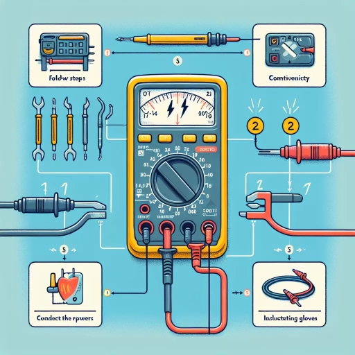
Conducting the Continuity Test with a Multimeter
When conducting a continuity test with a multimeter, it's essential to follow a systematic approach to ensure accurate results. First, set the multimeter to the continuity test mode, usually denoted by a musical note or a diode symbol. Next, ensure the circuit or component being tested is de-energized, as continuity testing requires a zero-voltage condition. Then, touch the multimeter's probes to the two points in the circuit or component where you want to check for continuity. The multimeter will beep or display a low resistance reading if there is continuity between the two points, indicating a good connection. If there is no beep or a high resistance reading, it indicates a break or open circuit. It's crucial to note that some multimeters may have a slight delay before beeping, so wait for a brief moment before concluding the test. Additionally, be aware that some components, such as capacitors and inductors, may show a low resistance reading due to their inherent properties, so it's essential to understand the component's characteristics before interpreting the results. By following these steps and considering the component's properties, you can accurately determine continuity and identify potential issues in your circuit or component.
Interpreting the Results of the Continuity Test
The results of a continuity test can be interpreted in a straightforward manner. If the multimeter beeps or shows a low resistance reading (usually less than 1 ohm), it indicates that there is continuity between the two test points. This means that the circuit is complete, and the current can flow freely. On the other hand, if the multimeter does not beep or shows a high resistance reading (usually greater than 1 megohm), it indicates that there is no continuity between the two test points. This means that the circuit is broken, and the current cannot flow. In some cases, the multimeter may show a moderate resistance reading (usually between 1 ohm and 1 megohm), which can indicate a faulty or damaged component, such as a resistor or a wire. In this case, further investigation is required to determine the cause of the problem. By interpreting the results of the continuity test, you can quickly identify whether a circuit is functioning correctly or not, and take corrective action to repair or replace faulty components.